
tl;dr – I wanted to see if I could make a computer controlled LED light strip to go under my desk. Turns out I can, this is how I built a LED light strip that's controlled by a Raspberry PI.
Disclaimer
This project involves working with mains electricity. Working with main electricity can be dangerous and you should not attempt this unless you know what you are doing.
The Goal
A set of RGB lights that I can use a Raspberry PI to control each LED and individually set the colour and brightness of each LED.
What You Will Need
I already had a soldering iron, solder, a spare Raspberry PI, connector blocks and a multimeter. In addition to these I also bought the following:
- sourcingmap 10.4"x7.2"x2.4"(263mmx182mmx60mm) ABS Junction Box Electric Project Enclosure Clear
- DC Power Plugs
- Crimp Connectors Electrical Wire Connectors Set - best used with some kind of crimping tool, or wire cutters that have a crimping slot
- Heat Shrink Tubing Electric Insulation
- MinRi Portable Mini Heat Gun
- Breadboard jumper wires
- BTF-LIGHTING WS2812b 30leds/Pixels/m Waterproof IP65 Black PCB Flexible Individually Addressable Strip Light Dream Color DC5V 16.4ft 5m
This should come with 2x 3-PIN JST SM Connectors. If it doesn't you can buy some more here. - LEADSTAR 5V 10A 50W Switching Power Supply Driver Converter Adapter for LED Strip
Step 1: Powering the Transformer
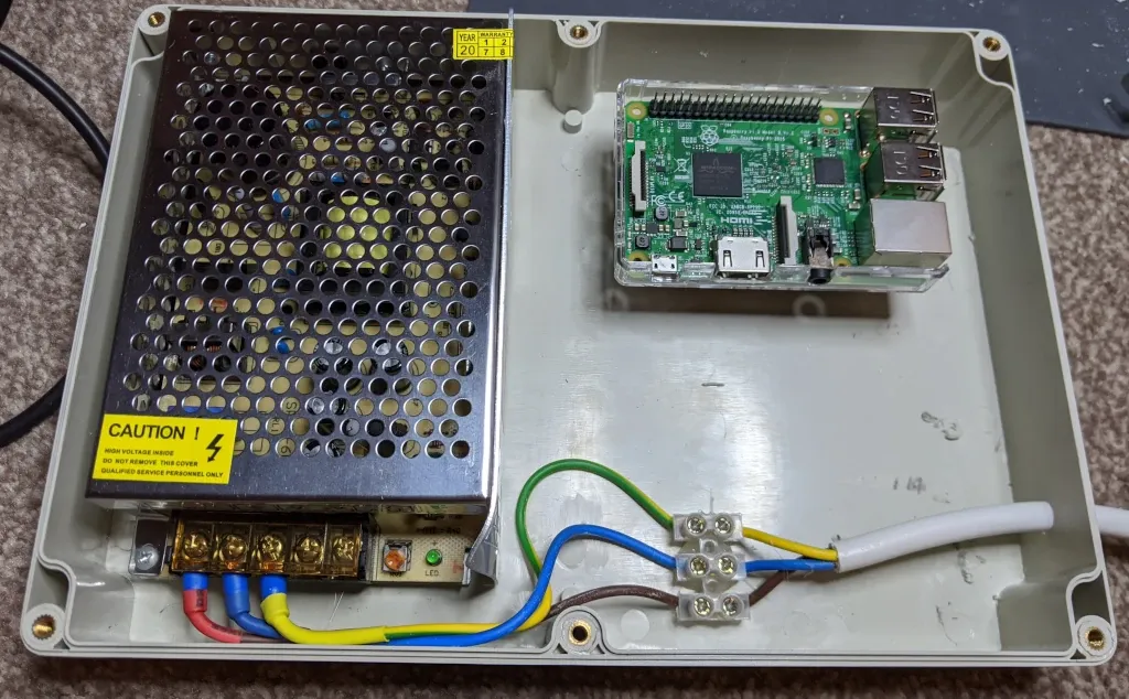
The first step is to wire up the transformer to a mains plug. For this I took around 1-1.5m of mains cable and attached a 13A fused plug to one end. The other end was then connected to the Live, Neutral and Earth terminal screw on the transformer.
As you can see for the picture below I used spade connectors to connect the wires easily onto the screw terminals:
- Strip the live, neutral and earth wires.
- Place a piece of heat shrink over each stripped wire that will be long enough to bind between the spade connector case and the wire
- Use pliers to remove the plastic case from three spade connectors and thread a case over each stripped wire
- Use a crimping tool to crimp the spade connector. You can use pliers if you don't have a crimping tool, but be careful not to bend the connector out of shape.
- Fit the plastic case back over the crimped connector
- Position the heat shrinks so they sit tightly over the plastic case of the crimped connected and carefully use a heat gun to shrink the heat shrink so that it binds to the cable and casing of the spade connector.
Before fixing the spade connectors into the screw terminals I used a multimeter to check the connection between each spade connector and its corresponding prong on the plug.
One the spade connectors are fitted to the screw terminals and you are happy with the wiring, it is time to plug in the transformer and see if it works.
If everything is wired up correctly the green LED should turn on.
The next step is to use a multimeter on DC output terminal screws (two right-most screws) to check the DC voltage. Initially mine was reading around ~4.5V, so using a screw driver I turned the orange screw between the screw terminals and the power indicator LED clockwise until I was getting an output of 5V.
Step 2: Fix the transformer inside the case
The next step is to fix the transformer in the box. Annoyingly the box has some plastic pegs which can get in the way. I've removed all of these apart from the ones by the top middle and bottom middle screw which don't get in the way.
You can remove the plastic pegs by using a multitool like I did, but you may leave behind scuff marks like I have. I have since learned that they can also be removed using a very sharp paid of wire cutters.
With the pegs removed I fixed the transformed to the case using glue-gun glue. I made sure to leave as much room around the terminal connections as possible.
You can now also drill a hole for the mains cable. In feeding my crimped mains cable through the whole the crimp connectors came off. They weren't held on particularly securely being my first attempts with the crimping tool. So I used a terminal block and some extra mains wire (with the outer plastic casing removed) to bridge the gap between the mains cable and the transformer.
Step 3: Fix the Pi inside the case
The Pi I'm using is a Raspberry Pi 3 Model B Rev 1.2 that I've had for a while. At the time I bought it I also purchased a clear plastic case. I have removed the top portion of the plastic case and have used a screw hole that was manufactured into the case to fix the Pi to a small block of wood. I have done this so that in the future I can easily remove the memory card if I need to. Raised up the Pi a couple of centimetres gives me enough clearance to get a figure underneath and coax out the memory card.
The block of wood is fixed to the case using glue-gun glue.
In positioning the Pi I have also taken care to leave a good gap round all sides that have ports so that I could plug in cables if I need to for troubleshooting issues with the Pi.
In the steps that follow always disconnect the transformer from the mains before adjusting or working on any wiring.
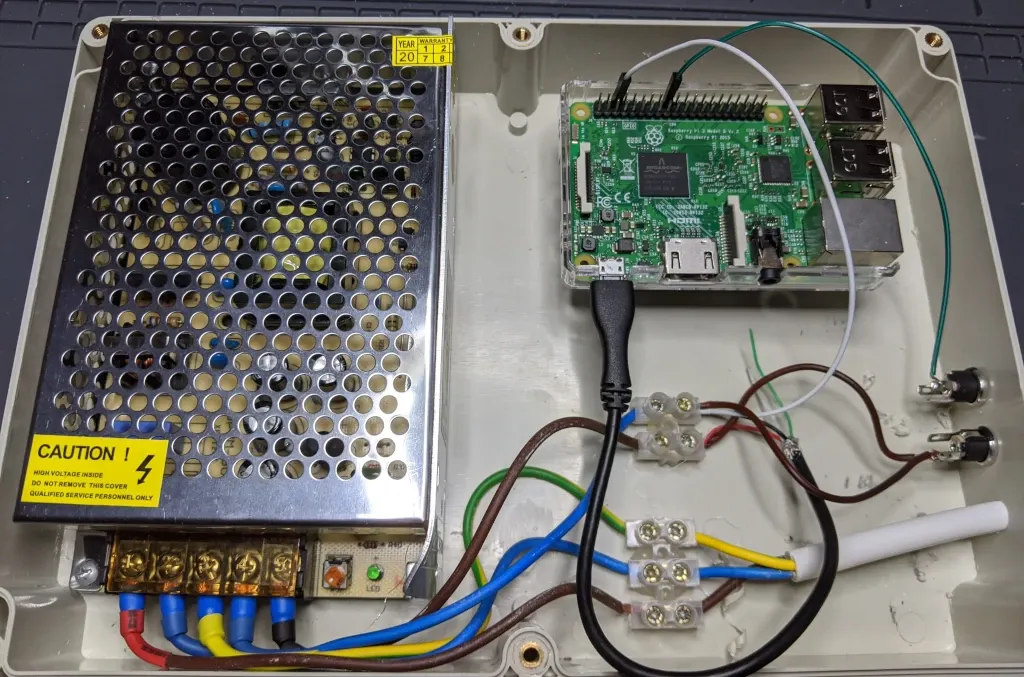
Step 4: Power the Pi
As the LEDs require 5V we can power the Raspberry Pi off of the same power supply to avoid having to power the Pi separately.
Start by running two cables from the DC terminals on the transformer to a terminal block.
You will also need to sacrifice a spare USB cable with a micro-USB connector. Cut off the micro-USB connector with 5-10cm of cable to play with. Strip back the outer plastic casing. This should leave you with a red, white, black and green cable:
- Red: 5V+
- Green: Data-
- White: Data+
- Black: 5V-
We don't care about the data wires, so wire up the red and black wires to the positive and negative of the transformers DC output.
In the image shown in the next step you will see that I take a brown wire for DC+ and a blue wire for DC- from the transformer to a terminal block of two connectors.
- The red USB wire (+) is wired up to my DC + wire (brown)
- The black USB wire (-) is wired up to my DC - wire (blue)
With this wired up correctly the Pi will power on.
Step 5: Power the Lights
Wiring up the lights is fairly straightforward. In my specific implementation I have decided to wire up the lights so that I can disconnect them from this box. To do this I use a pair of DC plugs and sockets. I used DC plugs and sockets for simplicity but you could use a single connector with more pins if you wanted (such as a din connector).
Each end of the LED light strip will have a pair or red and white wires for positive and negative and a 3-PIN JST SM which also includes a positive and negative as well as a green data wire. We will only need to connect to one end of the LED strip.
The picture below shows how I have taken a 3-PIN JST connector and used this to wire the data cable into a DC plug. The DC socket is wired using a breadboard jumper wire to GPIO18 on the Pi.
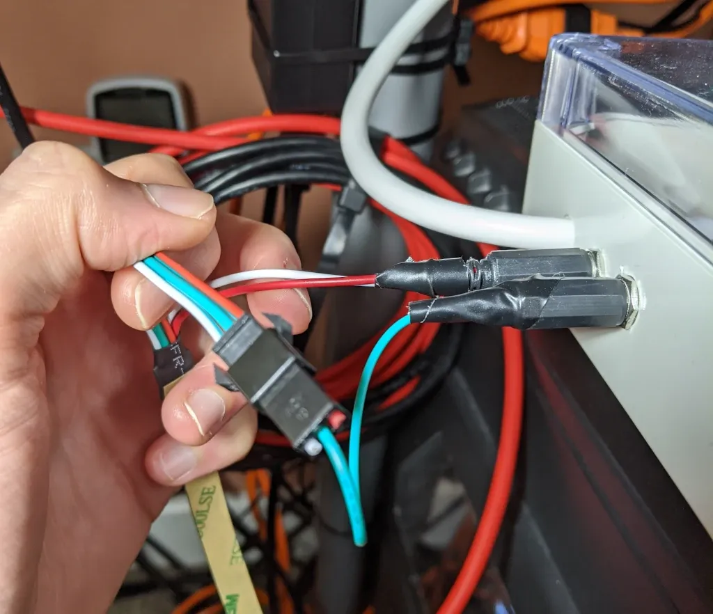
For the mains power I've done something similar where the pair of red and white wires are wired into the DC plug (wired such that the plug has a positive tip). The corresponding socket for this plug is wired into the DC+ and DC- for the transformer.
You will also need a white wire connecting DC- to a Ground pin on the Pi. Just like with the data cable I use a breadboard jumper to do this.
Step 6 - Temperature Sensor (Optional)
I happened to have a spare DHT22 temperature and humidity sensor lying around which I have decided to install to keep an eye on the temperature of the transformer.
The DHT22 sensor is wired into a 3V3 Power and Ground pins on the Pi with data running via GPIO17.
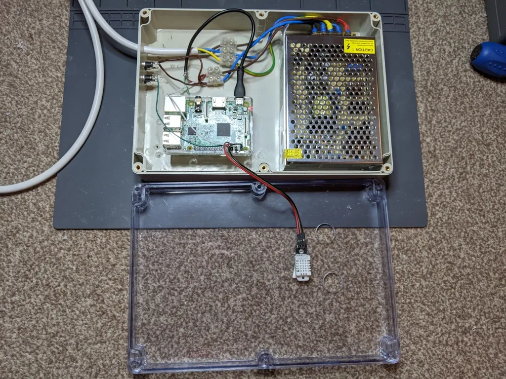
You will also see that I have drilled two air holes into the lid of the case. This may provide limited benefit without a fan. I've noticed for the most part the transformer runs around ~35°C, although it is likely to run hotter if the LED strip is set to full white which will draw the most power.
I will keep an eye on the temperature and will fit a 5V fan if needed.
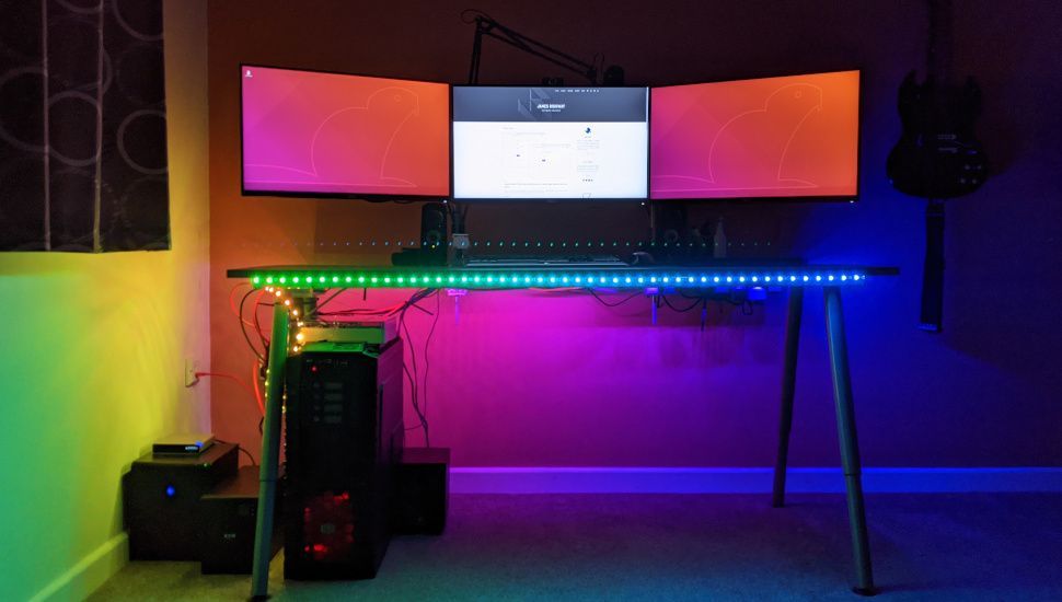
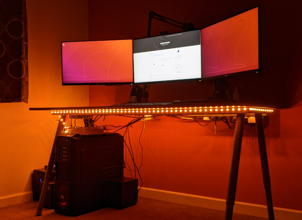
The End Result
And this is the end result – a LED light strip that can be fully controlled from a Raspberry Pi!
In the next blog post I will focus on the software side of this project – what libraries you need to control the light strip and how I've gone about controlling the LED strip.
